


The 411 on Basic Skeletal Modeling in Inventor.
- Mar 23, 2015
- 5 min read
The are different design philosophies such as the traditional ‘Bottom-Up‘ method, and the more elaborate ‘Top-Down’ approach. Skeletal Modeling is often referred to as the ‘Middle-Out’ technique. At it’s heart is the concept that a ‘Skeleton’ representation of a design drives the design itself. Any modification to this representation propagates throughout the model geometry. This enables design changes to be made quickly and easily by not having to tweak each component individually, but rather all at once.
The thought of tackling Skeletal modeling for the first time can seem daunting. Although this type of modeling has the potential to get very complicated, the knowledge needed up front to get started is very minimal. If you know the basics of Inventor than you already have most of the skillset needed to accomplish this. The fundamentals of part creation are all that is needed to get up and running.
The first step is to create a part file that will serve as our ‘Skeleton’ which will contain all the information for our design. I find that the best place to start is to create a ‘Layout’ sketch that will represent the overall shape of our assembly. We will add dimensions and parameters as we need to bring it together. Keep in mind it’s always a good idea to rename all relevant parameters and browser features. This will help to identify our ingredients when we start building components later on.


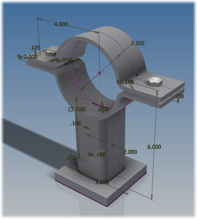
Here I have created a simple pipe bracket or pipe saddle. It consists of a ‘Base’ plate, a ‘Pedestal’, and a ‘Bracket’ that we will use top and bottom to mount and secure the pipe . We have a circle in the center that is set to the outside diameter of the pipe.
Once we have our layout done we will then start adding other sketches to use to build our components. We will add parameters to represent different aspects of this components. For example; renaming the length and width dimensional parameters for a plate and add a user parameter for it’s thickness. Rename the profile sketch to something relevant like “Plate_Profile”.

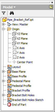
Here you can see we have added additional work planes and sketches for the different profiles we will use in ‘Extrude’ operations. In traditional part modeling we draw our profile and then extrude it to create geometry. In this approach we are adding all of our component sketches in one part and not creating any model geometry. We place these profiles relative to their positions in the actual assembly. This enables up to use very little if any Assembly Constraints in our assembly. We allow our part position to be dictated relative to the part’s coordinate origin.
After we have put in place everything we need, we will save our reference part giving it a name that represents it’s function. I like to add ‘_Ref’ to the end of the part's name. in this case I used ‘Pipe_Bracket_Ref.ipt’ for the name. How you organize the file structure of your assembly is up to you. The only thing to keep in mind is that all files involved should be in a relevant path specified in the Project file. (*.IPJ) It is never fun to have to sort out missing components due to a poorly configured Project file.
Next we will start to build our parts. Whether you create them from within an assembly, (Top-Down), or build the parts individually and bring them together after, (Bottom-Up), is entirely up to you. For the sake of simplicity we will create them individually.
We will create a new part file from our preferred part template and cancel sketch creation if our Application settings are set to do so automatically. We will them execute the ‘Derive’ command which can be found in the pull-down below the ‘Sweep’ command in the ‘Create’ section of the ‘3D Model’ tab. Upon execution we will be prompted for a file, (IPT or IAM) where we will browse to and select our reference file we saved earlier.

We will then be presented with the ‘Derive Part’ dialog box. By default everything that is available to reference into our new part is selected. We however want to select only a few things on a part by part basis. Select the name of the reference part in the top of the list and then click the the grey (/) circle above it. This will deselect everything for us. Then we will expand the individual sections and click the grey (/) circle next to those items we want to use for the one component we wish to create. Make sure to select any sketches, parameter and work features you need. The circle will turn yellow (+) to indicate that the items have been selected.
Do not worry about any of the other features in this dialog box at this time, as we do not require them. This tool enables us to do more, but we will not focus on these options now. Do make sure however that the ‘Scale factor’ is set to 1.000 ul and that the ‘Mirror part’ box is unchecked.

After we click ‘Ok’ we will now find the selected items in our new part file and ready to be used. If we missed anything, we can simply right click on the ‘Derive’ feature in the browse and ‘Edit Derived Part.’ We will them create our part geometry using our standard Inventor operations. We will repeat this for each component we wish to create saving each file.
It is now time to bring all our parts together into an assembly. We will create a new assembly file based on our template of choice. Once in the assembly we will start to place out components. Although it is no necessary, I prefer to place the reference (Skeleton) part into the assembly. This serves two purposes; the first is to have a visual reference for the placement of the other components and second, it’s presence makes adding iLogic rules to drive our design easier. We will place the reference by right clicking and selecting ‘Place Grounded at Origin.’

Alternately, we could use the ‘Ground and Root Component’ tool if we did a left click place. Note that in addition to grounding the component, the ‘Ground and Root Component’ tool also creates assembly constraints between the component and Assembly Origin Planes. This is referred to as ‘Rooting’ a component. Rooting a component locks it’s position in case it mistakenly become ungrounded.

Insert the remaining components in the same manner until the assembly is completely populated. We should end up with somthing like what we see below when finished.

One issue we want to avoid, if we chose to include our reference part into our assembly, is the fact that it will appear in our ‘Parts List.’ (drawing Bill of Material) To keep this hidden we will change it’s ‘BOM structure’ to ‘Reference. this can be done via the iProperties’ ‘Occurrence’ tab or in the ‘Bill of Materials’ tool.

In this example I choose to use the ‘Bracket’ part twice. We will insert a second ‘Bracket and using the ‘Grip Snap’ tool, reorient, position and ground the part into place. Note that I have used the origin of the reference part as the center of the pipe and brackets. This was done to help facilitate the second ‘Bracket’ placement. When we adjust our reference later on, our brackets will be symmetrical around the origin.

Once completed , any modification to our reference (Skeleton) part will be reflected in the assembly. Keep in mind that a ‘Local Update’ may be required after any modification, so keep an eye open for our friend the lightning Bolt in the ‘Quick Access’ bar at the top of Inventor.

I hope you found this helpful in taking a first step into Skeletal Modeling. Please feel free to leave any comments or questions you might have below. As always, you can find the model I’ve used in this example on GrabCAD.
Comments